一、Foreword
Stepper motor is the electrical pulse signal into the angular or linear displacement of the open-loop control elements. In the case of non-overload, motor speed, stopped position depends only on the pulse frequency and pulse number, regardless of load changes, that is, to add a pulse motor, the motor is turned one step angle. The presence of this linear relationship, with a periodic error of the stepping motor only without the accumulated error and so on. Makes the speed, position and other control areas with stepper motor to control becomes very simple.
While stepping motor has been widely used, but the stepper motor does not like an ordinary DC motor, AC motor in the conventional use. Stepper motor must be pulse signal power driver circuit composed of the control system can be used. So make good use of the stepper motor is not easy, it involves mechanical, electrical, electronic and computer and many other expertise.
Currently, the production of the stepper motor manufacturers do a lot, but with professional and technical personnel who can own development, development of the manufacturers is very small, most of the manufacturers in a blind imitation stage, which gives the user product selection, use lots of trouble. Given the above, we are here to describe the basic working principle of stepper motor, hope for the majority of users in the selection, use, and overall improvement when helpful.
|
二、Permanent magnet (PM-type) stepper motor principle
|
Permanent magnet (PM-type) stepper motor principle
Permanent magnet (PM type) stepping motor rotor is an inner rotor type (outside the stator, the middle of the air gap motor), the cylindrical outer surface of the rotor distribution n, s pole (outer surface without teeth). Two-phase stepper motor PM claw pole type structure shown in Figure 2.11. Stator windings are placed axially, of the phase winding is called the slave mounting structure.
A cylindrical permanent magnet rotor, the center of the output shaft is installed. A cylindrical outer circumferential surface of the permanent magnet are distributed alternately and s n pole pole, the pole pair number nr, n, s and a very polar distance. Its rotor pole through the air gap, facing the stator poles. Stator poles according to their shape called claw pole (clawpo1e), with a magnetic steel sheet metal forming, forming a claw pole nr. Two stator plates interact with their poles placed, a difference of 1/2 pole pitch. One of the rotor poles 2nr 2nr corresponding to one phase of the stator is formed.
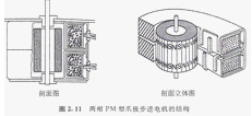
Stator winding is wound on a circular skeleton, made of circular coils. The two stators on the stator magnetic circuit the same, the difference of the adjacent pole 1/4 pole pitch, ie the deviation 90/nr. Two rotor poles corresponding agreement.
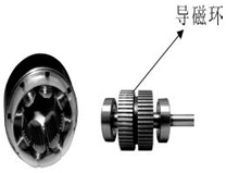
Stator claw pole type stepping motor, the air gap is o. 2mm, decided to step angle resolution θs = 90/nr. If nr = 5 ~ 12, the step angle θs of 1.8 to 75, usually 7.5. Figure 2.12 shows the appearance of the PM type stepping motor.
Two-phase claw pole PM type stepping motor works shown in Figure 2.14. The actual two-phase claw pole PM type stepping motor shown in Figure 2.11, the design of a multi-polar nr = 12, this time the number of claw pole stator has 12 pairs of pole per phase. To simplify the principle of ease of understanding, Figure 2.14 will be simplified into a pair of one-phase pole. Contrast Figure 2.11 and Figure 2.14, the actual two-phase stepper motor two phase winding excitation simultaneously, usually for two-phase excitation drive, easy to explain and understand, is a simplified description of the phase excitation state, a phase excited if they can drive the rotor rotates, the two-phase excitation certainly can operate.
Shown in Figure 2.14, stl, st2 two-phase stator windings, the coil winding direction shown. rt of the rotor, NdFeB magnets, n, s outer surface of the rotor pole distribution, and the working air gap is formed between the stator pole. Figure know, a phase coil excitation poles a pair of stators, the rotor and the stator pole pair number of pole pairs of the same pitch, the adjacent rotor pole s will attract each other and the n-side, electromagnetic force is generated.
A first step, Fig. 2.14 (a) l-phase coil is excited diagram of stl rotor and stator poles attract each sex. If the external force is applied at this time, the rotor will move with the load, the electromagnetic force generated figure 2.14 (a) the position shown in the restoring force of the force determines the size of the load position accuracy. In this case, 2-phase stator poles st2 centerline of the rotor poles n, s the middle pole, 2-phase stator and rotor poles away from the center line of π / 2, the displacement angle of a step angle.
The second step, Figure 2.14 (b) in, stl coil current is off, st2 of the coil current becomes on. Move the rotor π / 2, the rotor is attracted st2 stopped.
The third step, Figure 2.14 (c) in, stl coil current reverse energized stator polarity reversal, the rotor then rotates π / 2 after the rest.
The fourth step, FIG 2 14 (d) in, st2 reverse energized coil current. Stator polarity reversal, the rotor then rotates π / 2 after the rest.
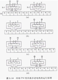
Then return to Figure 2.14 (a), followed by (b), (c), (d) repeated cycles, constant rotation. Above for the two-phase PM claw pole type stepping motor operating principle.
According to the above description, a step angle rotor pole pole pitch l / 2, go to step 4 for a loop. Step angle by the number of poles of the rotor is determined, the number of poles on the stator torque increase impact. Of course, this type of a unipolar stepping motor (uni-polar) and the bipolar type (b1 a polar) type, are accompanied by the rotation of the stator magnetic poles, the reverse is also the same.
三、Reaction (VR type) stepper motor principle
1、Structure:
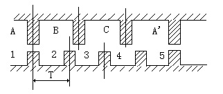
Rotor evenly distributed with many small teeth, there are three exciter stator tooth winding, respectively, and in turn its geometric axis rotor tooth axis staggered.
0,1 / 3 te, 2/3, te, (between the axes of two adjacent rotor tooth pitch distance is expressed in te), A is aligned with the tooth 1, B 2 and the teeth shifted to the right 1/3 te, shifted to the right and the tooth 3 C 2/3 te, A ’is aligned with the teeth 5, (A’ is a, the tooth 5 is tooth 1) the following is a development view of the stator and rotor:
2、Rotate:
If the A-phase is energized, B, C phase is not energized, the magnetic field, alignment of the teeth 1 and A, (rotor without any force following are the same).
Such as the B-phase power, A, C phase is not energized, the teeth 2 and B should be the alignment of the rotor to the right than 1/3 of the te, time shift tooth C 3 and 1/3 te, teeth 4 and A offset (te -1 / 3 down) = 2/3 te.
For example, C phase power, A, B phase is not energized, the teeth 3 should be aligned with the C, then the rotor ED also right over 1/3 te, the teeth 4 and the A time offset is 1/3 te alignment.
If the A-phase is energized, B, C phase is not energized, the teeth 4 are aligned A rotor ED also right over 1/3 te, so that after A, B, C, A are energized, the teeth 4 (i.e., a previous tooth 1 teeth) to the A-phase, right around a rotor tooth pitch, if constantly press A, B, C, A ...... energized, the motor on each step (per pulse) 1/3 te, rotate right. In terms of A, C, B, A ...... energized, the motor reversal.
This shows that: the motor position and velocity of a conductive frequency (number of pulses) and frequency of a one to one relationship. The direction is determined by conducting sequential decision.
However, out of torque, smooth, noise and reduce the angle and other considerations. Often using A-AB-B-BC-C-CA-A this conductive state, so that each step of the original 1/3 te changed to 1/6 te. Even through different combinations of two-phase current, making it 1/3 te becomes 1/12 te, 1/24 te, which is the basic theory of motor subdivision driven basis.
Difficult Release: The motor stator has m-phase excitation winding, respectively, the axis of the rotor tooth axis offset 1 / m, 2 / m ...... (m-1) / m, 1. The conductive phase sequence according to a certain reversing motor can be controlled - it is the physical conditions of the stepping motor rotation. As long as we meet this condition can theoretically create any phase stepper motor, for cost and many other considerations, the market generally two, three, four, five phases as much.
3、Moment:
Once the motor is energized, the magnetic field is generated between the stator and rotor (flux Ф) when the rotor and stator stagger angle to generate forces
F and (dФ / dθ) is proportional to the
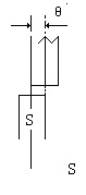
Its flux Ф=Br*S
Br is the flux density, S is permeable area
F is proportional to L * D * Br
L is the effective length of the core, D is the rotor diameter
Br=N・I/R
N ・ I is the excitation winding ampere turns (current multiplied by the number of turns) R is reluctance.
Torque = force * radius
* Motor torque and the effective volume flux density is proportional to the ampere-turns * (only consider the linear state)
Thus, the effective volume of the larger motors, the magnetizing ampere turns greater, the smaller the air gap between stator and rotor, motor torque, and vice versa.
四、Hybrid (HB type) stepper motor principle
1Two-phase hybrid stepping motor structure
Used in industrial control shown in Figure 4.1 with small teeth on the stator poles, the rotor teeth a lot of structure, the step angle can be made very small. Figure 4.1 two-phase hybrid stepping motor diagram, and Figure 4.2 stepper motor winding wiring diagram, A, B two-phase winding phase separation radially along the circumference of the stator has 8 poles protruding, 1, 3,5,7 poles belonging to the A-phase winding, 2,4,6,8 poles belonging to the B-phase windings, the stator pole face each have five teeth, most who have control winding. And the ends of the ring magnet rotor core composition, the central ring magnet in the rotor, axial magnetization, two cores were installed at both ends of the magnet so that the rotor axis is divided into two poles. Evenly distributed on the rotor core 50 teeth, the teeth on the two core staggered half a tooth pitch, the teeth of the stator and rotor tooth pitch and the same width.
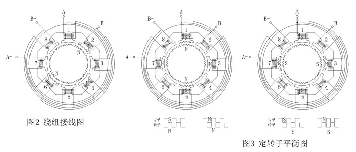
2Two-phase hybrid stepping motor works
When the two-phase control winding by 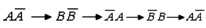 The order in turn energized, each phase winding is energized only one shot, form a four-beat cycle. When the control winding current is passed through, they produce magnetic momentum, it is with the permanent magnet magnetomotive force produced by the interaction of electromagnetic torque, the rotor produces a step movement.
A phase winding is energized, the rotor N terminal pole 1 the windings of the S poles attract the rotor N pole, so that the magnetic pole 1 under the tooth-to-tooth, magnetic lines of force from the rotor N pole pointing pole 1 of the tooth surface, the magnetic pole 5 also under tooth for tooth, tooth poles 3 and 7 are on the slots, as shown in Figure 4.4 A phase energized stator and rotor rotor N extreme equilibrium diagram. Since the two rotor core teeth staggered by half a tooth distance, the S pole of the rotor, magnetic poles 1 ’and 5’ S pole magnetic field generated, exclusion S pole rotor, and the rotor teeth in the slot just the pole 3 ’and 7 ’N pole magnetic field generated tooth surface to attract the rotor S pole, so that tooth-to-tooth. A phase winding is energized extreme rotor N, S extreme rotor balance is shown in Figure 4.3.
Because there are 50 teeth on the rotor, the pitch angle of 360 ° / 50 = 7.2 °, the share of the stator teeth per pole pitch is not an integer, so when the A-phase stator is energized, the rotor N pole, the pole 1 5 teeth and rotor teeth of the tooth, next to the B-phase windings of the five magnetic pole teeth 2 and the rotor teeth are 1/4 pitch of the dislocation, i.e. 1.8 °, Figure 4.4 shows the A-phase stator and rotor teeth is energized Expand Figure circular motion where, A phase 3 pole teeth and the rotor will be misplaced 3.6 °, to achieve a tooth on the slot. Magnetic field lines of the rotor N-terminal → A (1) S pole magnetic ring → → A (3 ’) N → rotor pole rotor S → N-terminal end, into a closed curve. A phase B phase powered off, generates N-polar magnetic poles 2, pull the nearest S pole of the rotor teeth 7, so that the rotor in the clockwise direction 1.8 °, to achieve the rotor pole teeth of the gear 2, B phase Expand the rotor windings are energized tooth shown in Figure 4.5, case 3 and the rotor pole teeth are 1/4 pitch of dislocation. And so if it continues to press the four-beat sequence is energized, the rotor on one step clockwise rotation of power once every one pulse per rotor to turn 1.8 °, which said step angle of 1.8 °, the rotor turned around required 360 ° / 1.8 ° = 200 pulses (see Figure 4.4, 4.5).
In extreme rotor S is the same token, when the winding tooth-to-tooth, its pole next to a phase dislocation 1.8 °.
|